Carrier Piping Design Manual Pdf
Carrier piping design manual pdf. The 30RB also communicates with other building management systems via. The piping design of any air conditioning system will affect the performance reliability and applied cost of that system. High lift design Equivalent pipe length of 125m and vertical lift of 50m is made possible with TOSHIBA Super HRM.
Part 3 Carrier System Design Manual by Carrier Air Conditioning Company Paperback 5900 Only 1 left in stock - order soon. The heat recovery system uses a multi-port distribution controller which acts as a central location allowing better refrigerant distribution to. Ily chilled water and condenser water system piping system design it is important to understand the evolution from 1-pipe into the other three systems all of which are used for heating as well as cooling.
CARRIER Series New Edition Part 3 Piping Design. 41 out of 5 stars 21. Carrier Design Manual.
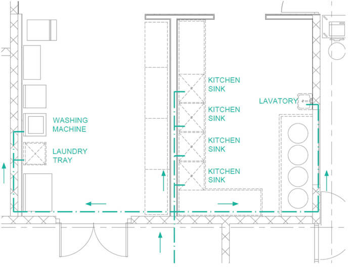
1-Pipe Systems A 1-pipe water distribution system is a system that has a one main pipe looping around the building and then returning. F piping design-genaral 1 SYSTEM DESIGN MANUAL SUMMARY OF PART THREE water piping 2 This part of the System Design Manual presents data and examples to the engineer in practical design and layout of normal air conditioning piping system. Flexible modular design compact size and user-friendly con-trols make the 30MP chillers an opti-.
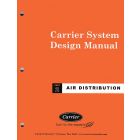
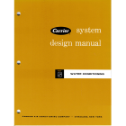
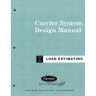
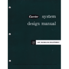
Refrigerant Piping Design Goals A common goal is to size the Suction Hot Gas and Liquid lines for about 1Fº pressure drop at design capacity. Manual Index Part 1 - Load estimating Part 2 - Air Distribution Part 3 - Piping Design Part 4 - Refrigerants. Get carrier piping design manual PDF file for free from our online library CARRIER PIPING DESIGN MANUAL INTRODUCTION The main topic of this pdf is mainly lined about CARRIER PIPING DESIGN MANUAL.
Part 3 Carrier System Design Manual Carrier Air. The program contains data for three common refrigerants R-22 R-134a and R-717 permitting comfort cooling as well as low temperature applications to be examined. Suitable to precisely match the buildings cooling and heating demands Carrier VRF systems utilize a 2-pipe system for both heat pump and heat recovery.
Pdf Carrier System Design Manual Part 3 Piping - Searches related to pdf carrier system design manual part 3 piping design. Carrier Engineering Manual number 3.
Pdf Carrier System Design Manual Part 3 Piping - Searches related to pdf carrier system design manual part 3 piping design.
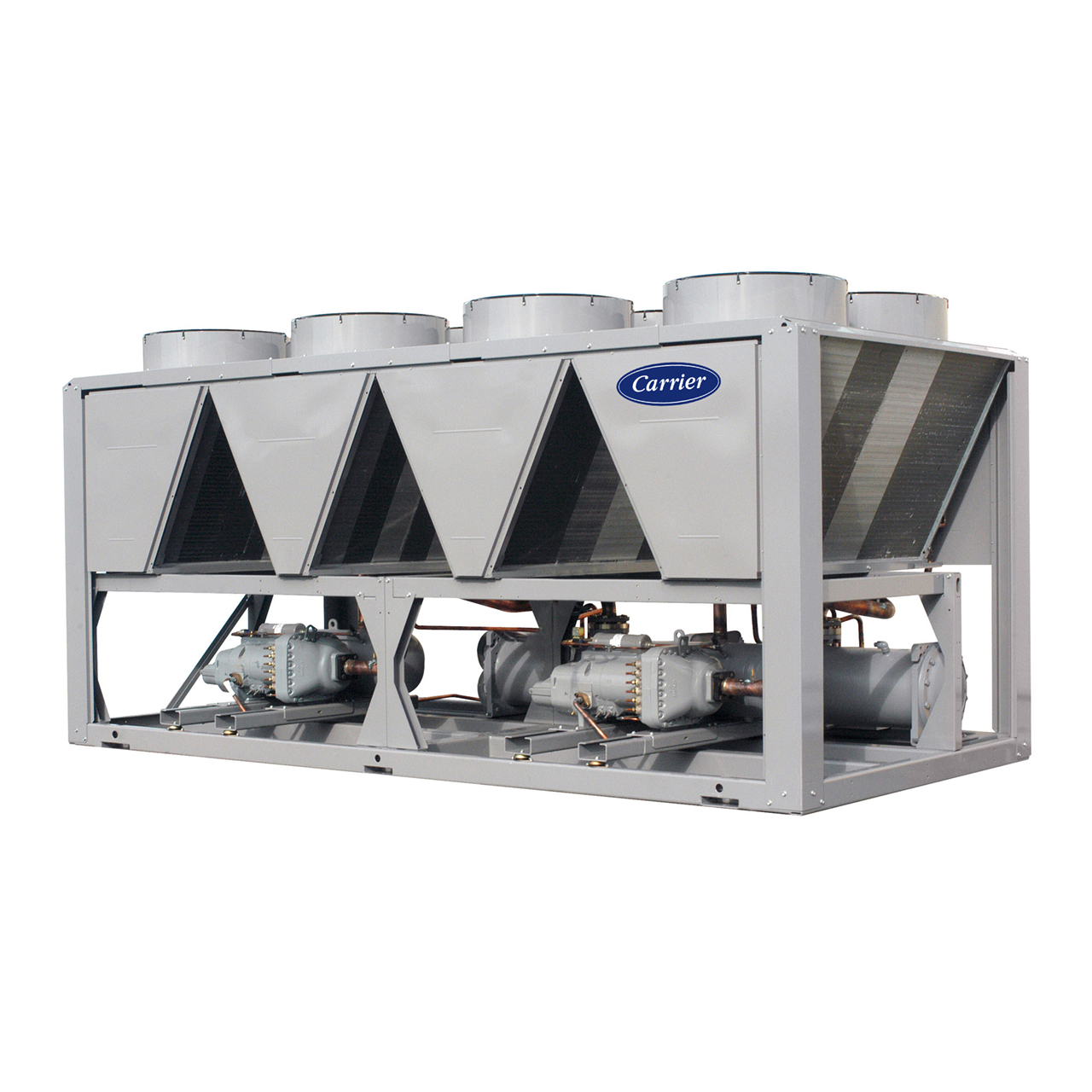
Refrigerant Piping Design Check List The first step in refrigerant piping design is to gather product and jobsite information. This single-circuit modular chiller covers a wide range of applications from ice to heat recovery and various combinations can be eas-ily designed to meet the required plant capacity. How this information is used will be explained throughout the rest of this guide. Refrigerant piping 3 The text of this. Manual Index Part 1 - Load estimating Part 2 - Air Distribution Part 3 - Piping Design Part 4 - Refrigerants. DESIGN GUIDELINES ¾Steam T racing ¾C lean Steam ¾Piping Trapping TYPICAL PIPING SCHEMATICS ¾O ven Heating Coils ¾Shell Tube Heat Exchanger ¾Ve ssel With Steam Coil - Top Outlet ¾U nit Heater ¾Flat Work Ironer ¾S team Press ¾Jacketed Pressure Vessel ¾P ressure Vessel With Dimple Jacket. Ships from and sold by RocketCert Books Training. Carrier Design Manual. In keeping with industry standards the Refrigerant Piping Design program calculations are based on procedures outlined in the ASHRAE Refrigeration Handbook.
The heat recovery system uses a multi-port distribution controller which acts as a central location allowing better refrigerant distribution to. Get carrier piping design manual PDF file for free from our online library CARRIER PIPING DESIGN MANUAL INTRODUCTION The main topic of this pdf is mainly lined about CARRIER PIPING DESIGN MANUAL. Refrigerant Piping Design Check List The first step in refrigerant piping design is to gather product and jobsite information. Suitable to precisely match the buildings cooling and heating demands Carrier VRF systems utilize a 2-pipe system for both heat pump and heat recovery. Carrier equipment through the CCN Carrier Comfort Network - proprietary protocol all components form a HVAC system fully-integrated and balanced through one of the Carriers network system products like the Chiller System Manager or the Plant System Manager optional. Carrier Engineering Manual number 3. Ily chilled water and condenser water system piping system design it is important to understand the evolution from 1-pipe into the other three systems all of which are used for heating as well as cooling.















Post a Comment for "Carrier Piping Design Manual Pdf"